


WALL ASSEMBLY AXONOMETRIC COLOR PDF VERSION
In simple terms, the wall of a house separates inside from outside, protects us from the elements and provides privacy. The walls hold up the roof and the lofts and are a substantial part of a projects material and construction time when all said and done. When those walls are on a mobile platform they have to withstand pretty extreme vibrations and lateral forces that are introduced during transportation and need to be ready for a wide range of potential environments while being as light weight as possible.
So let’s nerd out about the how’s and why of our unique wall assembly and structure for a few minutes. This is meant more as a quick go to resource when fielding the inevitable questions to come and is not an instruction manual or negative commentary on what others have done. This is what we did and why we think we will benefit from those decisions. We will include some links to pertinent past posts and photos but you can view our continually updated VISUAL GALLERY to browse hundreds of build process photos and some videos that will bring you up to speed, starting at day 1.
Before reading this it is important to understand a few things:
- The thermal and structural performance of a material and the thermal and structural performance of an assembly are two, very different things.
- A Tiny House On Wheels (THOW) is a very different structure than a house on a foundation and the forces on a THOW are a bit different from the forces on a regular sized home and therefore we propose the structure should be considered from a new perspective.
- Studs combat gravity loads (vertical) and the sheathing (plywood) combats the lateral (sideways) loads by adding what is called shear strength.
While our final wall assembly design was the result of careful and simultaneous structural AND thermal considerations, we will address each of them separately below.
STRUCTURE


To clarify, let’s look at an occurrence you would find in an average sized home (on a foundation); a trussed roof span of 30’ with trusses installed 24” on center. With a 75 lb roof load, the tributary area of a single truss in this system is 60 square feet, resulting in a 4,500 pound load being supported by that single truss. That load is then split and distributed to its two end bearing points resulting in a 2,250 pound load being supported by the wall studs on each side. This is not considered a big load in the construction industry and is easily supported by standard wall construction.
Now let’s apply this same analysis to our (and many other) tiny houses. We use a 2×6 rafter positioned 2 feet on center, spanning 8’. Under the same 75 lb roof load the 16 sf of tributary area produces a 600 lb point load on each end. This is an incredibly small point load in the world of construction. Now this singular instance of a 600lbs point load is actually pretty conservative (high) especially in our area that uses a code regulated 50 pound per square foot snow load as worst case scenario, And while that point load is pushing the acceptable limits of a single free standing 2×3 stud, the use of frame, skin, paneling and insulation in a unified system increased the strength of the whole. This is a great example of the whole being stronger than the sum of its parts.
If you are still feeling hesitant on our decision to use 2x3s, consider this; When talking about the axial loading of a stud in these instances, we are worried about failure through buckling (bending) not crushing, that is why the acceptable load is increased if the stud, or column is “braced”. Which is what the studs are in the context of a wall with glued and screwed sheathing on each side and rigid foam packed in between.
It was when researching RV’s and their use of a 2×2 structural frame that we began considering the potential for options other than the standard 2×4 THOW framing and what benefits could result in the form of reduced weight, added space and/or improved thermal performance. Clearly, there are a lot of differences between a D.I.Y THOW and a manufactured and engineered RV, but taking inspiration from the RV’s ability to reduce its structural frame and weight by making all of the elements work together as a system; most notably through lamination of the frame and skin was an important moment in our thought process and was the foundation for our first decisions.
Below are the bullet points for our THOW construction decisions as well as a few corresponding photos:
- We screwed and glued our skin to our frame on both sides of the wall (our interior plywood paneling and our exterior plywood sheathing) in an attempt to make them act as one.
- We used 3/8” plywood instead of ½” plywood sheathing.
- We used 2×3 lumber instead of 2×4 lumber for our vertical structure and placed the studs 24” on center instead of 16” on center.
- We used double stud corners instead of triple stud corners, eliminated jack studs at openings (instead using header hangers) and we used a single top plate in lieu of a double top plate.
- This could be referred to as a form of advanced framing and was first experimented with as a way to reduce lumber (and thus costs) and then adopted by the green building movement who embraced the reduced thermal bridging that comes with that decrease in lumber. For us, reducing the amount of lumber means reducing the amount of weight of our structure and helps us avoid exceeding the 10,000 lb rating of our trailer axles. In reality, even if we had a trailer that could hold 15,000 lbs, we would prefer not to have to pull that much. The results of these decisions also have important thermal performance considerations we will discuss in a bit.
- Our roof rafters are spaced 2’ on center, span side to side and are aligned above the vertical studs as required with a single top plate because it would not be able to support potential roof loads if the rafter was bearing at mid span of the top plate between studs.
- On the long walls of our house, the sheathing extends up past our top plate and over the ends of our rafters and are glued and screwed to them in order to attach the roof system to the wall system.


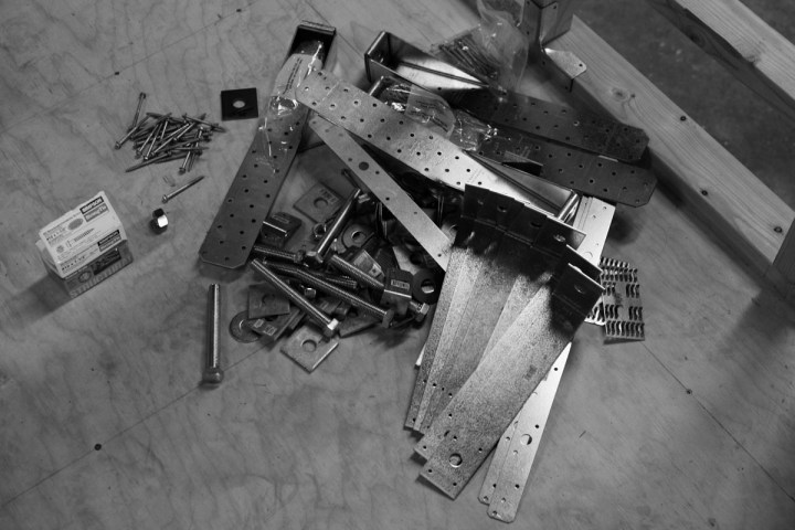
- We installed heavy duty tension tie down hardware in 8 spots at the base of our walls, including our four corners. This hardware secures the vertical structure to the trailer. We also used small steel angles to secure each stud to the bottom plate. It is important to note that if you only secure the bottom plate to the trailer, you run the risk of your studs separating from your bottom plate during strong racking or uplift forces because the couple of nails or screws used to tack your walls together before lifting them have very little resistance against withdrawal. If you want to learn a little more about our floor system, trailer choice and why it made securing our walls to the trailer so easy and efficient check out THIS POST.


- We used slabs of rigid foam, cut on a table saw and installed snugly between studs to hopefully increase the walls rigidity although while this certainly does not hurt, it is unlikely that it will have much structural effect if the walls are constructed properly with a completely adhered skin. It also helped create sturdier feeling 1/4″ interior plywood walls by providing a solid backing support.
- We detailed our loft in such a way to prevent the creation of a lateral weak point by eliminating a break in our framing at the loft and running the studs the full height of the wall. We then detailed the connection of the horizontal loft beams to the vertical wall structure in a manner to help resist lateral forces. We have done this by using two beams, one on each side of the stud combined with steel “T” brackets in an attempt to transform a moment in the structure that usually acts as a hinge joint into a more rigid connection by distribute the forces vertically and horizontally along the members, away from the traditional pivot point.


THERMAL PERFORMANCE


To better understand why the use of continuous insulation is beneficial, it is important to understand the difference between the performance of a material and the performance of an assembly. If you pack your 2×4 wall cavity (which is 3.5” deep) with rigid foam board rated at R-5 per inch you would assume your insulation value to be 17.5” (+ a little more for sheathing, siding, etc…) This is only partially correct however when you consider that your wood studs have an r-value of only around 1.25 per inch. So while the space between your studs may meet your assumed r-value, the r-value of the entire wall assembly is reduced due to the occurrence of “thermal bridging” which is when unwanted energy takes the path of least resistance through the studs that have a dramatically reduced R-value. To show this using a simple example lets look at a 4×8 section of a standard wall. This section of wall has 4608 square inches of surface area. With studs at 16” on center and at a height of 91.5” plus the bottom plate and double top plate that is around 628 square inches of wood in just that small section of wall. That is 13.6 percent of your wall assembly that is low r-value wood spanning through and bypassing your insulation from the interior paneling all the way to your exterior sheathing and siding. (This number can be higher when you account for doubling up of studs at windows and other overbuilding occurrences)
Our choice to reduce the amount of lumber in our walls in order to save weight now benefits us in a second way by reducing the amount of studs, jack studs, and top plates where thermal bridging would have occurred. On top of this, the use of a continuous insulation around the exterior of our home means that thermal bridging is significantly reduced because our framing is protected from exterior temperatures by an inch of rigid insulation. In a nutshell: less wood means less thermal bridging and more space for insulation and the addition of 1” of continuous insulation results in a wall assembly equal in thickness to that of a 2×4 wall but with better thermal performance because of reduced thermal bridging.
Some other interesting facts about our wall assembly:
Our siding is reclaimed corrugated metal panels that spent the first 50 years of their life on the roof of a local apple bin canopy before being salvaged during structure demolition and incorporated into our tiny house thanks to the help of Steve at LEADING FORCE ENERGY AND DESIGN CENTER. In addition to saving it from the landfill, this material offered a lot of benefits to our project:

The corrugation is only ½” thick from the outside of the concave curve to the outside of its opposite convex curve. Its low profile makes it a good option for a THOW where the builders are trying to maximize the interior space while staying under the 8’-6” max. width regulation (for non-permit travel). The metal panels are also lighter than comparable thickness wood siding.
We were pretty adamant about using a “rain screen” siding system that operates under the assumption that it is not if, but when moisture will make its way behind your siding and therefore takes measures to attempt to create a pressure equalization chamber and to ensure that the water that does make it past the cladding has a path to drain and air has a way to enter and exit to aid in the breathing/drying process. This is usually achieved by leaving a small space between the face of your building paper and the backside of your siding. This gap is often achieved through the addition of furring strips that act as spacers but we were able to utilize the beneficial characteristics of the vertical corrugations intrinsic to our metal panels to have vertical voids behind our siding for water drainage and air circulation.
Additionally these 2’x12’ metal panels are faster to install than smaller plank systems, create less seams, are made from non-organic material (will not rot), and eliminates maintenance as they do not require surface preparation or painting and are non-combustible. We also happen to really like the agriculture industrial aesthetic of this beautiful material that is steeped in Yakima Valley history and is almost symbolic of the valleys sun, sweat and labor, offering an incredible way to tie our project to the agricultural spirit that this city was built on.


